Mechanical design
This Weeks Assignment is to Design the Mechanical Part of the final Project and since my Final Project is basically an electromechanical System it has a lot of mechanics involved my plan of attack is to break down the system into sub systems and starting bottom up, but keeping in mind the KISS rule so you(The Reader) will not find complex geometry or lots of curves
Project: ROSADP
Goal: CAD the all the SUB-Systems of the projects
Files For this Assignment can be found here
Let the Dance Begin !!!
First I started thinking about the scale of the project and how big it was going to be and after a bit of looking around I found that a ~300x300x300 bounding Box would be good enough also this means i can almost cut ever part of the frame and sub systems on our laser cutter Awesome
Now let’s look at the Mobile Base
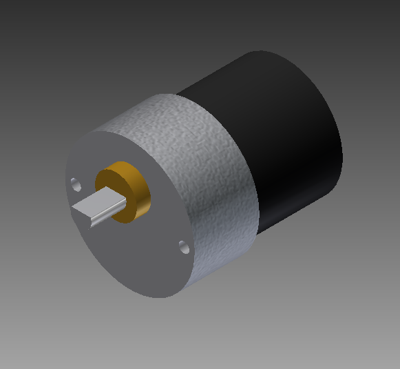
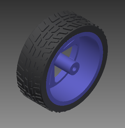
1st of all i need to design the Standard Components that can’t be altered
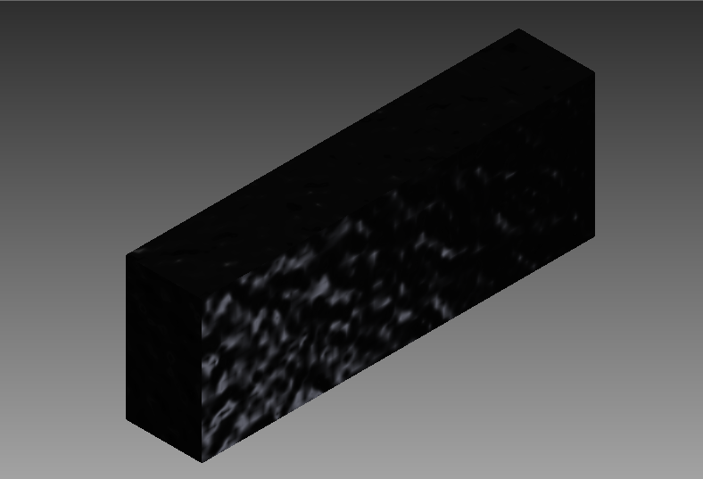
which include the Motor Battery Sensors Wheels etc
After that we can start to design around them I fancy the Interlocking cross construction Method Where you have several pieces that press into each other and the more you have the stronger it becomes because of the nature of the material used.
like the one found here http://makezine.com/2012/04/13/cnc-panel-joinery-notebook/
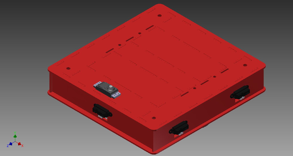
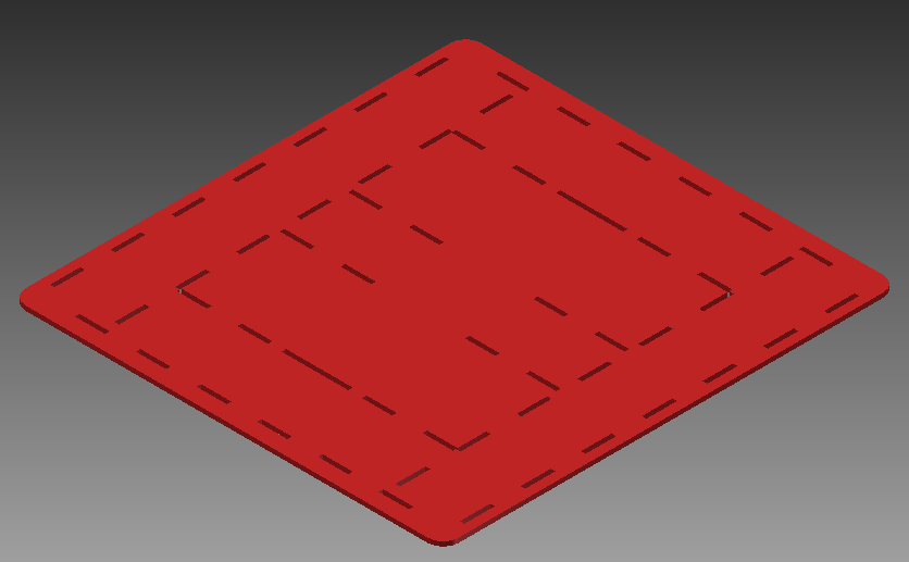
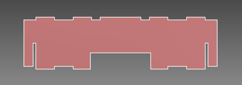
So i started the design out with building out the pieces starting with the base
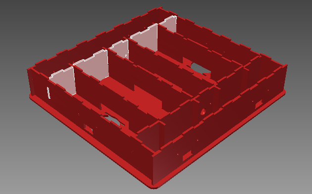
And after that the cross pieces which hole the main components as well as make up the main structure of the body
Designing Several Pieces with the same core concept that are derived from each other so basically using each pice to create the next so that they are almost all linked so when one changes the other adapt "Pseudo Parametric Design"
and after a few pieces and bit virtual puzzle solving we get this maze of slices
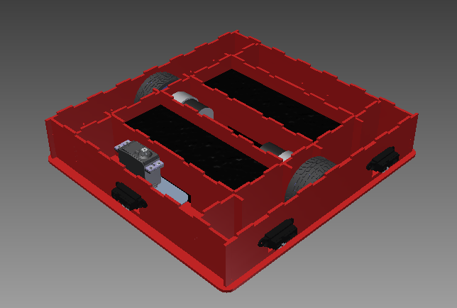
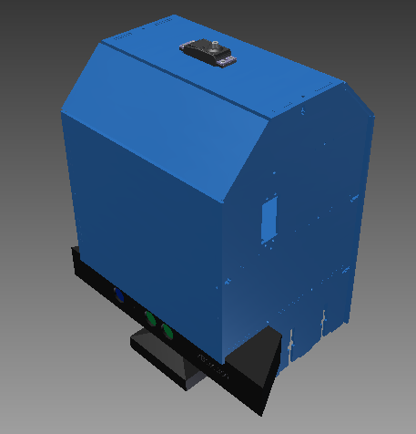
And after dropping in the Components
Selling it off
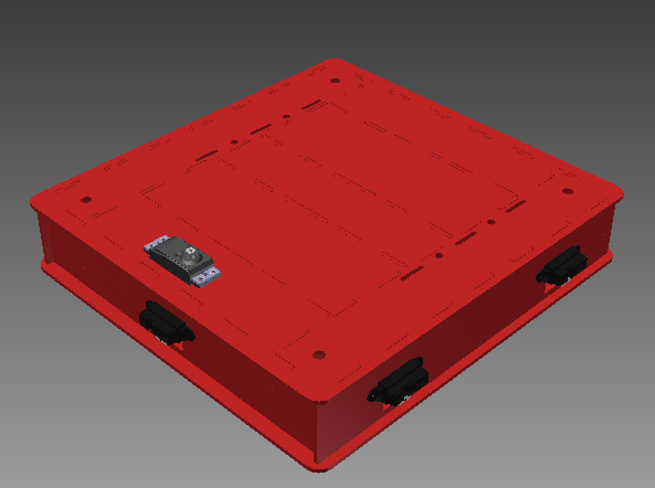
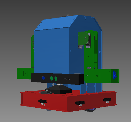
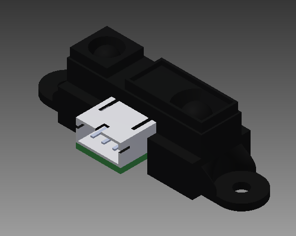
Now we have a Base this base is based around the differential Drive Steering and thus has only to wheels with caster front and back for balance and support also mounting for 6 IR Distance Sensors like the ones used in the Input Devices Week Found Here
also a Servo Motor is add in the very front for adding a custom Sonar Scanner but this is in a later stage
on of the problems that i faced when designing and building this like this in the past was something that might seem trivial to most but once you hit it you know can be a pain in the neck its leveling all the contact point since the motor wheel combos are of differing proportions than the caster wheels so i have to level the caster by adding spacers to the 2 mounting points of the casters easy enough just draw them up and 3d print time (or CNC Turn them Logical choice but no access to a lathe cnc or manual at this time)
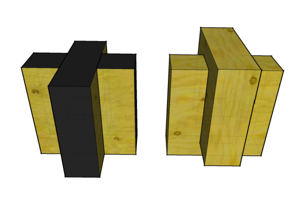
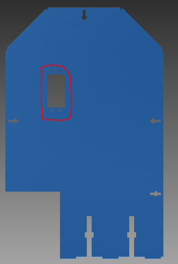
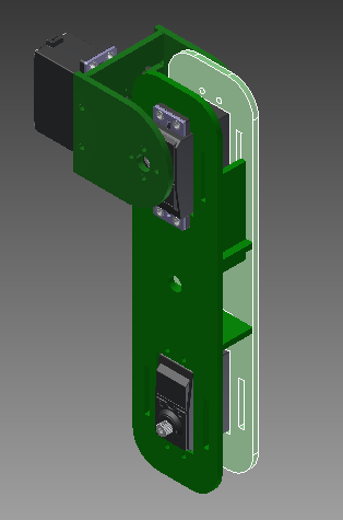
Now we Start on the Torso where all the electronics are going to get mounted as well as linking the mobile base to the Arms and head
To be honest there is not a lot to be said about the torso is built to be strong rigid and has enough room for all the Electronics
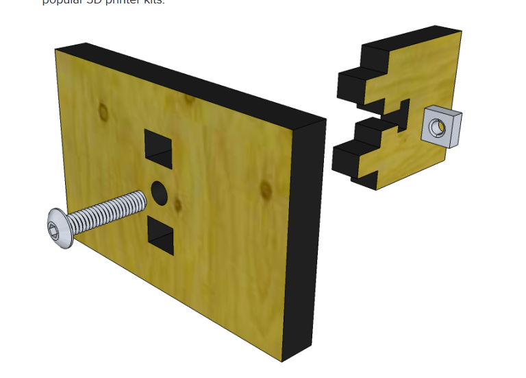
in this designed i used the T-Slot assembly method which gave it the strength it required with out using up much space in reinforcement
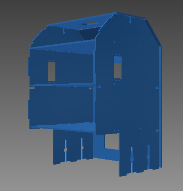
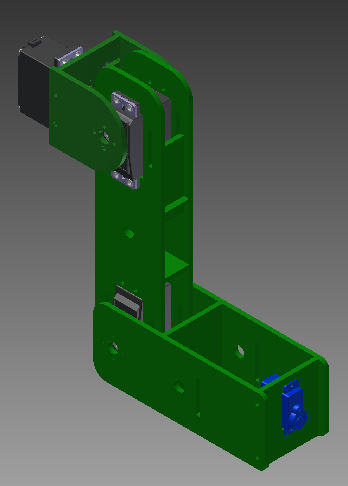
Drawing it up i kept in mind the 2 Arms that will get attached to the structures whish are a big deal where they need to be mounted over The CG (Center of gravity) of the entire machine
and after that it was a matter of adding the cross members and the skin
Now we Go Over to the arms the last of the main Sub-Systems
The arm is quite a bit tricky to design because you have to keep in mind the length of each joint in relation to the torque of the motor
but using http://www.societyofrobots.com/robot_arm_calculator.shtml
it gave some rough estimates to go one and the design begins
Starting at the shoulder

And working down the biceps
And to the forearm
The arm
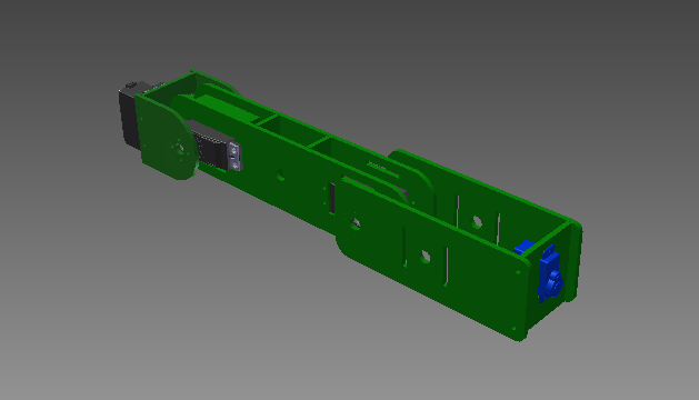
has 4DOF (Degrees Of Freedom) Which allow for a great range of motion they are:
- Shoulder Pitch
- Shoulder yaw
- Ell bow yaw
- Wrist pitch

and after that the basic shape of the arm was complete it is still missing the en effector though we there will be no end effector there well be only a plate with magnets and connector attached to the Wrist Roll Motor so that then you can add any custom Gripper, Vacuum Gripper, Injector, etc you want
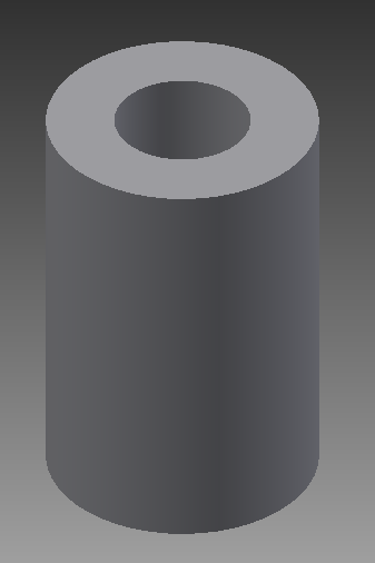
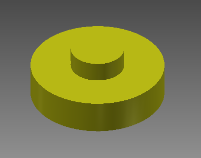
P.S: After a bit of experanting i added these 3d printed puck's to the back side of the servos ro go throuh to the next plate over and allow for support on both sides
putting them all together gives out this very unique looking robot